Frame
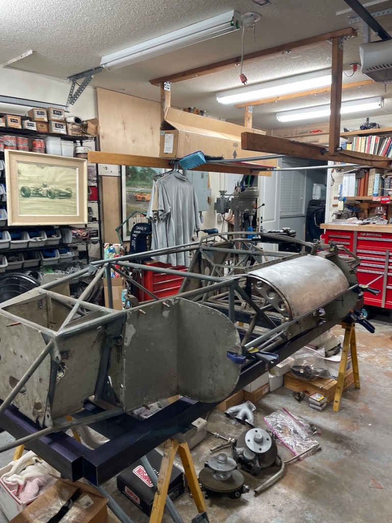
The frame for the car is in terrible shape. Having been made out of 35/1000 wall mild steel tubing it has not faired well with time. The car did have a shunt after dad sold it and has gone through a few ones.
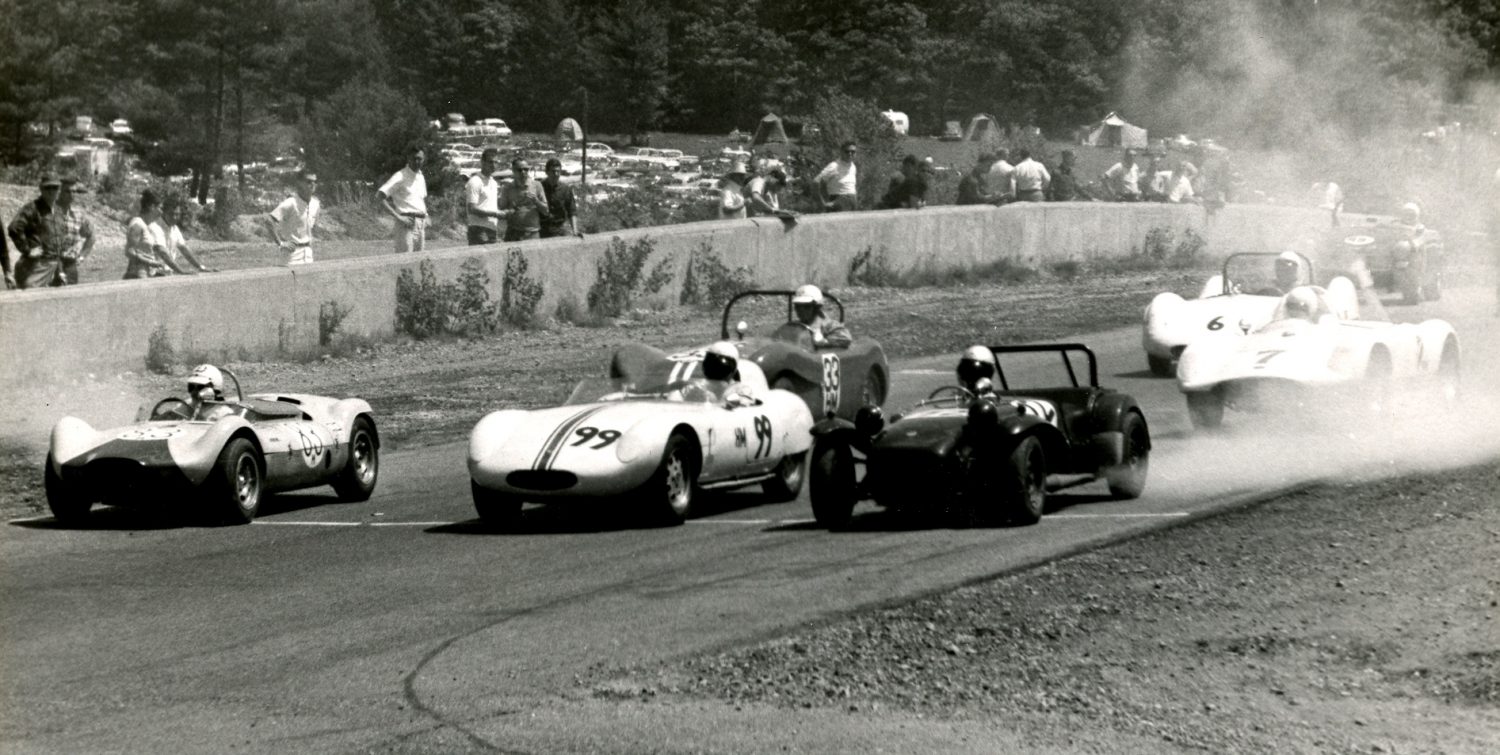
So begins the project of building a new frame. This time out of 65/1000 DOM tubing. Rather than gas weld it like Ed Zink did in his basement I have created a dedicated jig that will get the project strait and square and it will be big welded.
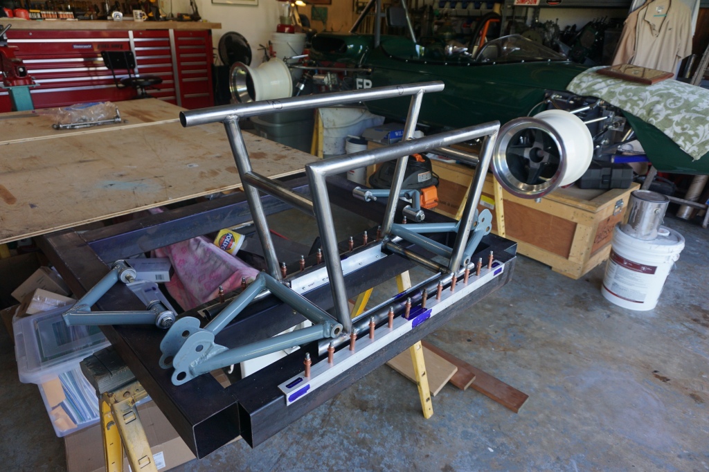
Here are some images of the frame on the dedicated jig. I was trying to see where all the inner aluminum panels went and finding the frame has quite a twist to it.
Yes the shop is a mess!!

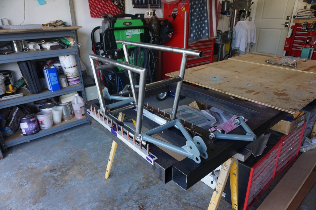
The first step was to create a master jig that will support the new frame. Next was creating a jig to form the first and second stations trapezoid’s for the front upper and lower suspension mount points and foot pedals . Here is the assembled nose box sitting on the jig. I created the jig using birch plywood and aluminum 1″ angle iron on a full scale drawing of the forward frame members on the plywood based off the original blue prints.
The next jig will be the side sections creating the box that the driver sits in and the rear suspension and engine mount too.


Here is the front suspension support box that also will contain the foot pedals.


The next step is to create the lower mount point jig and have the support point water jet to exact angels .
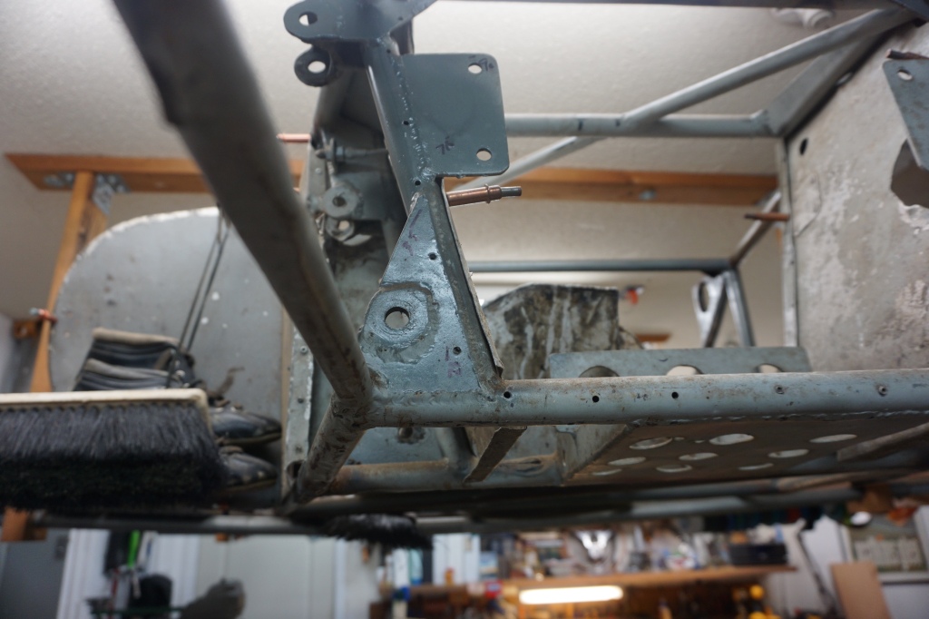
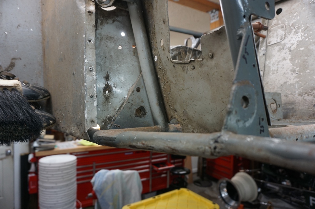
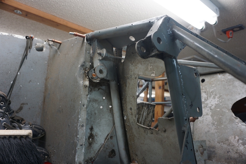
Here are images of the old mount points for reference of what is next to do. Ed was pretty basic with the frame mount points using 1/8 inch steel with a washer welded to the mount point. The new mount points are machined mount points then welded into the 1/8 inch triangular steel mounts, located on the front and rear trapezoids.

Here is the left suspension upright tentatively in place. I noted there are differences from frame versus the original blue print. Most notably the spindle upright is shorter than the original drawing and hence the upper geometry is a slightly lower. I intent to use the original frame points for upper due to the difference.
Here is the lower mount points in place. I do need to adjust the jig by cutting away the area underneath the lower A arm so I can allow it to drop and allow the upper A arm to be level.
Lots and lots of Cleco’s

Lower suspension points in place with the secure jig
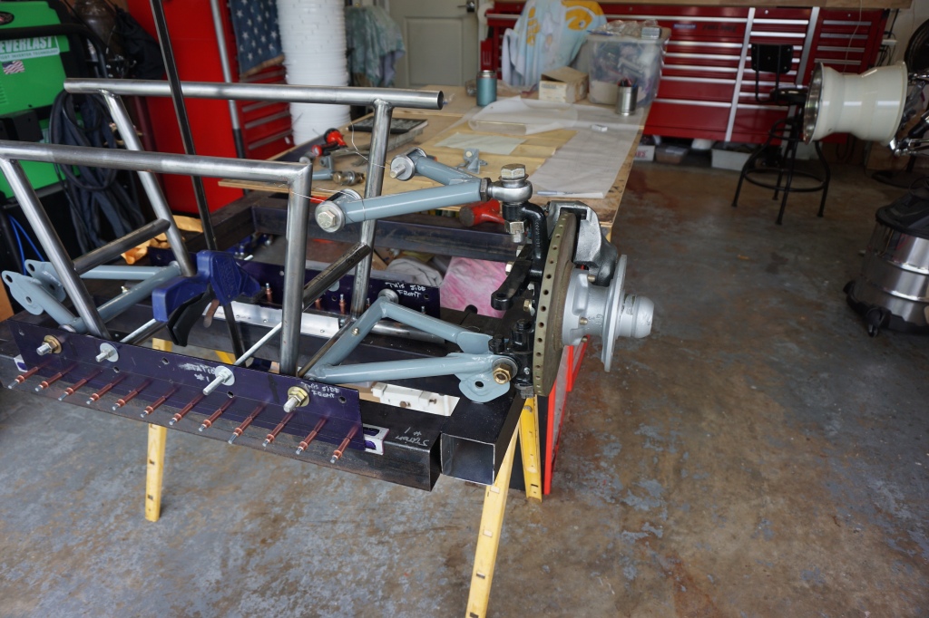
The lower A arm I will use the existing frame measurements and blue print dimensions. The upper A arm will be based on the actual frame and will base it’s measurements on the original frame due to the shorter spindle upright
In addition I am putting cross tubes in that will create a stronger and safer front suspension nose box. Dad complained that the frame creaked allot when racing. I am sure this was in part due to the lack of reinforcing structure
